Stepper motor control

The block controls the triggering of a stepper motor controller over a step/direction interface. With that, the stepper motor driver creates the needed current flow for a connected stepper motor, so it executes the desired number of steps.
Example: Experimental setup with STG-570, STG-700 and stepper motor
These video tutorials show you how you can easily implement a stepper motor control function block in a project. Here you can find the entire video tutorial "Experimental setup with STG-570, STG-700 and stepper motor".
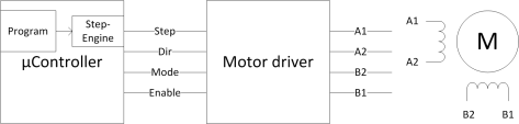
In the picture you can see, that besides step and direction (“Step“, “Dir”), two control signals are used for the stepper mode (“Mode”) and the enabling of the driver (“Enable”).
The basic work method is the following:
At the input “wPos” the setpoint for the position (number of steps) is preset. At the output “cPos” the current position is constantly returned. The output “Ready” signals, whether the setpoint and the current position match.
Over the input “StepRate” the number of steps per second can be adjusted.
If the input “Enable” is set to HIGH now, the motor driver will be activated. After that, a timer is started, which generates interrupts with the set speed. As long as “wPos” and “cPos” are different, one step is generated with each call, and the current position is updated in the interrupt service routine. That means that the execution is generally done independently from the program cycle time.
If the setpoint position is bigger than the actual position, the rotation is executed clockwise and the other way around counterclockwise.
If the motor is connected “twisted”, the rotation direction can be inverted by setting “DirInver” on HIGH.
All inputs can be edited while the application is running. Changes are immediately applied at the next block call.
The motor can f. e. hold a position by setting the “StepRate” on 0 and leaving “Enable” on HIGH. The maximum achievable stepper speed depends on the motor and the properties of the current supply. If the motor driver is triggered with a step speed which is too high, it might be that the motor “loses” steps or does not rotate at all anymore.
If a reference switch is used, it can be used to set the actual position on 0 by applying a HIGH at “PosReset”.
Parameters
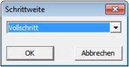
Over the parameter dialog the step size per step can be set:
- Full step
- Half step
- 1/4 step
- 1/8 step
A stepper motor has the highest holding torque when it is triggered with full steps. In contrast, smooth running increases with smaller step sizes (micro stepping).
Signals
| Name | I/O | Type(s) | Function |
|---|---|---|---|
| wPos | I | LONG | Setpoint for the step position |
| StepRate | I | WORD | Step speed (0..2500) Unit: Steps/seconds |
| DirInver | I | BIT | Reverse rotation direction 0 .. Clockwise rotation 1 .. Counterclockwise rotation |
| PosReset | I | BIT | Reset the current position 0 .. Do nothing 1 .. Current position is set to 0 |
| Enable | I | BIT | Activation of approach 0 .. turn off current supply for motor 1 .. Trigger motor |
| cPos | O | LONG | Current step position |
| Ready | O | BIT | Respond target achieved 0 .. setpoint and actual value do not match 1 .. setpoint and actual value are identical |