MODBUS Slave Configuration
1. Basic configuration

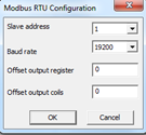
The basic characteristics of the Modbus RTU slaves are determined in a dialog, which is accessible over the tools menu.

Here, the slave address and the baud rate are defined. Further settings of the serial interface are fixed (no parity, 1 stopbit).

Furthermore address offsets for “Holding register” and/or “Coils” can be defined. Be aware, that these offsets are added automatically on the already assigned addresses. With very high addresses, this can lead to overflows. It is checked while entering into run mode and additionally when downloading. It might be reported as error.
2. Appoint an address

Addressing is 0 based. The addresses can be assigned for a range between 0 and 65535. Be aware, that when assigning an offset for “Holding register” and/or “Coils”, address conflicts might subsequently occur. At the latest, they are detected and marked while downloading.
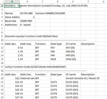
During each download, also during a download into the simulation, a description of all assigned addresses and the thereby connected I/Os and/or process variables are generated. This description is placed in the according project folder named [project name].MOBCSV. It is an Excel CSV file. When renaming it with *.CSV, it can be opened in MS Excel.
3. Assigning the data type and/or function

As the controllers, on which this library can be used, is freely (graphically) programmable, the process image is not predefined. Only the I/O functions are described by the hardware. For that reason there is the possibility to assign I/O functions or variables to the hardware.
The variable assignment is done through connection lines. The option “I/O” (1) has to be unchecked in the parameter dialog. For “Coils” or “Discrete inputs”, the data type (2) is set to bit. For “Input registers” or “Holding registers” a data type can be selected. Accordingly, the needed registers are automatically calculated. After closing the parameter dialog with “OK”, a pin is set at the according space. A variable of the right type can be assigned there.
Additionally a description for the entry can be implemented. It can then be found in the address list, which is recreated after each download.

The assignment of functions is done by setting the option “I/O” in the parameter dialog before the according line. Depending on the previously chosen function (“Coils”, “Discrete inputs”, “Holding register”, “Input register”) all available I/O functions are provided in a dropdown list.

Inputs („Discrete inputs“, „Input register“) require no special attention.
Outputs (“Coils”, “Holding registers”) have to be used in a way that no conflicts occur with the outputs used in the application.
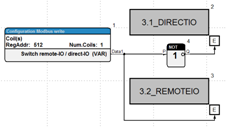
If the outputs are written in the application and through “Modbus accesses”, the accesses should be latched against each other as shown in the example.


