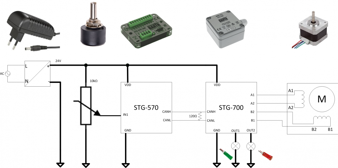
Experimental setup with STG-570, STG-700 and stepper motor
Part 1 - Introduction and technical characteristics
Part 3 - First steps with miCon-L
Part 4 - How to program the PLCs in accordance with the experimental setup
In this video series we will explain step by step how to program the setup shown in the picture.

Part 1 - Introduction and technical details
keywords: STG-570 CAN, STG-700 STEP, stepper motor, LED, potentiometer
Technical characteristics of the BARTH mini PLC lococube® STG-570 CAN and STG-700 STEP are described in part 1. Furthermore all parts, which are necessary for the setup are shown.
The parts for the experimental setup can be ordered at the RS Components webshop.
If the video does not work, you can click here to watch.
The STG-570 CAN mini-PLC provides:
- 3 analog Inputs 0 to 30 VDC, 12 bit ADC
- 2 digital Inputs up to 1 kHz
- 4 Power Outputs up to 1.5 A
- 1 Power PWM Output 2 A/1 to 10 kHz
- 1 CAN 2.0A/B Interface
- Reliable Solid-State Outputs
- Fail Safe Oscillator
- Programmable Status LED
- TTL-232/USB connection to PC
- Intuitive graphical programming capability
- Wide operating voltage range 7 to 32 VDC
- Wide operating temperature range -40 to +70°C
- Vibration resistant and rugged sealing
- super-flat housing of only 11 mm
The STG-700 STEP mini-PLC provides:
- 2 analog Inputs 0 to 30 VDC, 12 bit ADC
- 2 digital Inputs up to 1 kHz
- 4 Power Outputs up to 1.5 A
- 1 CAN 2.0A/B Interface
- Stepper Motor Output 1.5A bipolar
- Reliable Solid-State Outputs
- Fail Safe Oscillator
- Programmable Status LED
- TTL-232/USB Connection to PC
- Intuitive graphical Programming Capability
- Wide Operating Voltage Range 8 to 32 VDC
- Wide Operating Temp. Range -40 to +50°C
- Vibration resistant and rugged Sealing
- Protection Grade IP 66
Essential parts from the RS webshop which are used in this setup
Bipolar stepper motor from Sanyo Denki
- Step angle 1.8°
- Voltage Rating 24 VDC
- Frame Size 42x42 mm
- Current Rating 1 A
- Winding Arrangement bipolar
LED Indicators from APEM
Potentiometer from RS Pro:
- resistance 10 kΩ
- Power Rating 1 W
- of turns 1
Optional Parts from the RS webshop
2.5mm DC-Power socket from RS Pro
- Voltage Rating 12 VDC
- Power Rating 5 A
Equipment wire from RS Pro
- Cross sectional area 0.22 mm2
- Current Rating 1.4 A
Plug in Power Supply from RS Pro
- Input Voltage 230 V
- Output Voltage 24 V
- Output Current 1.5 A
- Comes with four interchangeable mains plugs
Part 2 – Experimental setup - How to assemble the parts
Part 2 of the video series explains the application and how the parts work together. An explanation about what part does what is given. It is necessary for programming the PLCs later on.
The general idea of the experimental setup is the following: When twisting the potentiometer, the PLCs are going to transform the voltage into a digital input and transfer the information to the stepper motor. The stepper motor will be able to make a 360° rotation depending on speed, direction and angle the potentiometer is twisted. Furthermore the red and green LED will indicate the direction of the stepper motor.
If the video does not work, you can click here to watch.
Part 3 - First steps with miCon-L
keywords: download miCon-L, block diagram, connection, download, realtime, online mode, User interface, project tree, configuration, program block, macro block, function block, library, worksheet, menu, toolbar, context menu, edit, edit mode
If the video does not work, you can click here to watch.
Part 3 introduces miCon-L and shows how to download and install the software. You will get a look into the user interface of the programming software and how you can watch your application in realtime. The forum as well as the miCon-L portal is introduced in this video, too. It is your main source to find documentation and help in all miCon-L matters.
Part 4 – How to program the PLCs in accordance with the experimental setup
keywords: connect PC with PLC, COM port, template, CAN Controller Init/Info, CAN send message, CAN receive message, CAN controller status, baud rate, visualization blocks, CAN ID, stepper motor, step rate, convert block, cycle time, run mode, task properties
Part 4 will finally explain how to program the PLCs and the CAN bus interface in a very simple way. Step by step and block by block we are building the application so you can fully understand what you are doing. This video is especially meant for beginners in miCon-L and graphical programming. It will show you how easy it is to start programming.
Here you can find the demo applications as zip files for download.
If the video does not work, you can click here to watch.
Part 5 – How to achieve a smoother running motor
keywords: micro step, switch, limiter, average, hysteresis, comparator, online mode, download, task properties, configuration, cycle time, CAN Controller Init/Info, CAN send message, CAN receive message, CAN controller status, CAN ID
If the video does not work, you can click here to watch.
Part 5 is built on the previous video, part 4 of this series. The application has been developed and we added a few steps in the application, so the stepper motor will run smoother and more quietly. The additional program strings are explained properly.
Here you can find the demo applications as zip files for download:
We hope you have found the demo useful and it helped to better understand the power of the BARTH mini PLCs and the capability of the free miCon-L software from ProSign. If you will experience issues by replicating the above demo, or while you are trying to expand it with further functionality, please take a look in the miCon-L forum which covers the most common FAQs, but also provides online support.
If you like this kind of tutorials please leave us a note with your wishes of further projects like this. The above is really just a basic start, BARTH mini PLCs and miCon-L from ProSign can do much more...challenge us.