Experimental setup with the STG-600
Connect the mini PLC to a computer and start the software.
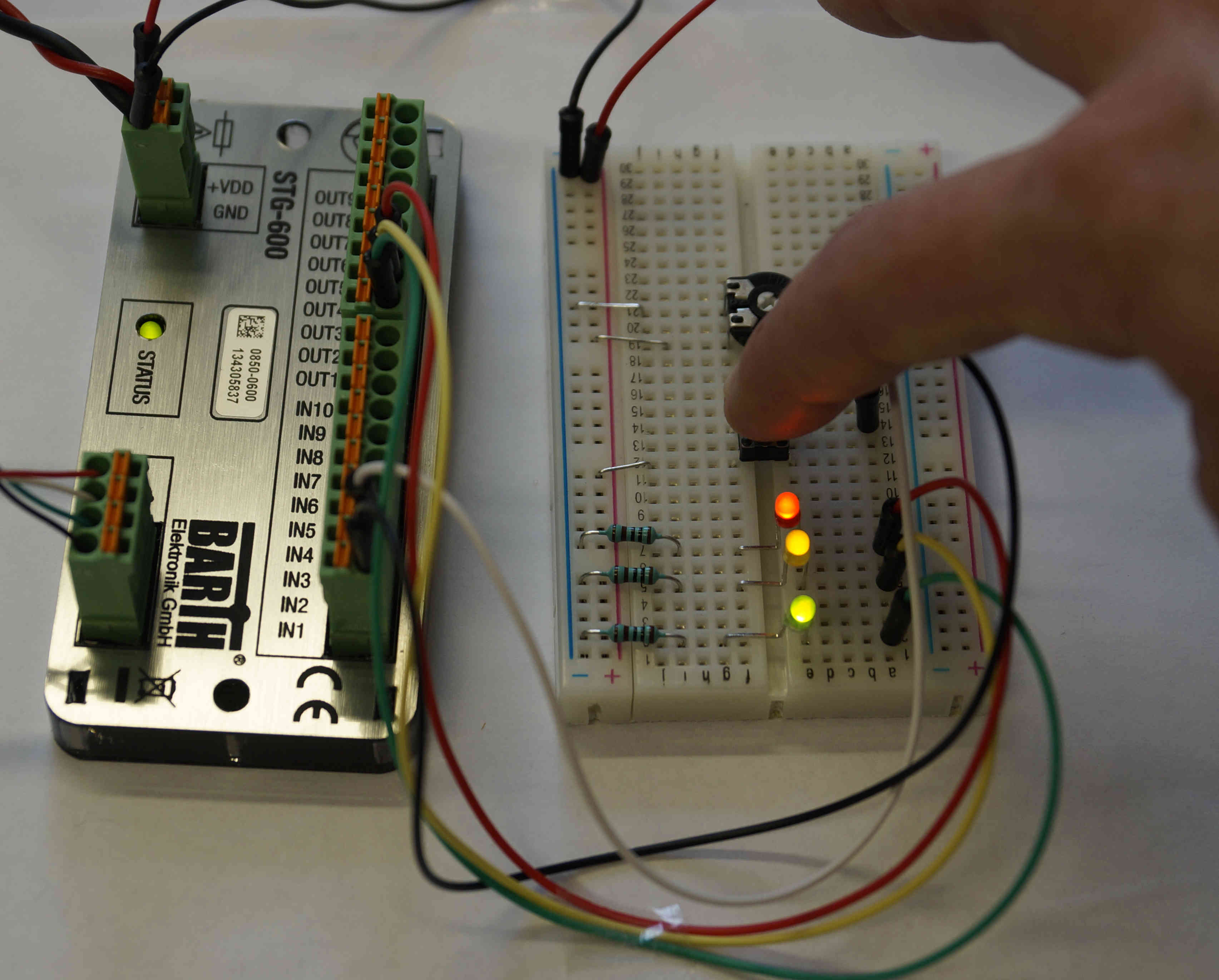
In the experimental setup, the STG-600 is connected to a potentiometer, a switch and 3 LEDs.
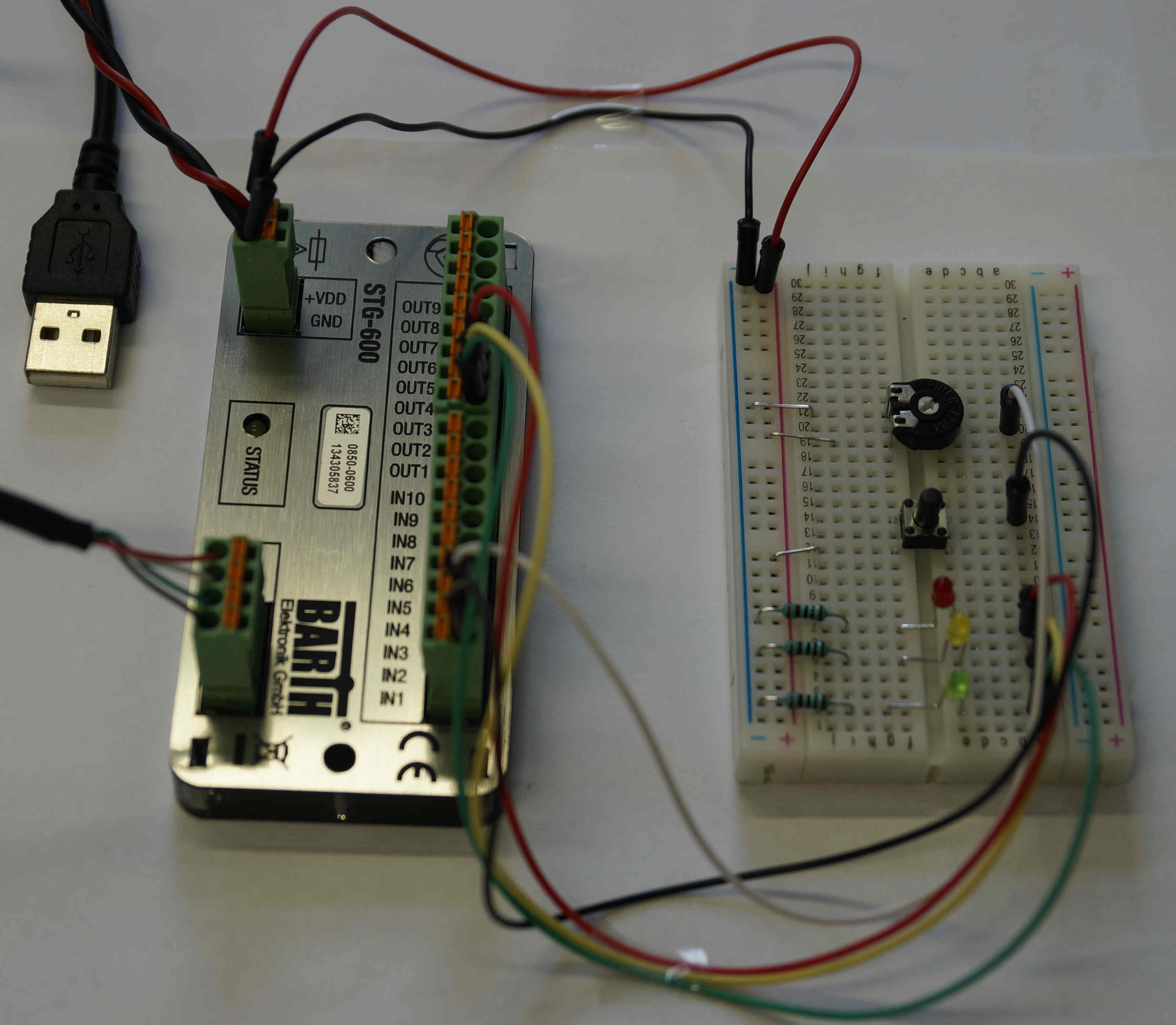
The inputs and outputs at the hardware are assigned as following:
| IN1 | switch |
| IN3 | potentiometer |
| OUT1 | green LED |
| OUT2 | yellow LED |
| OUT3 | red LED |
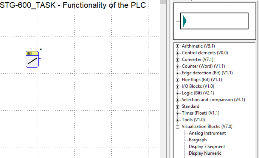
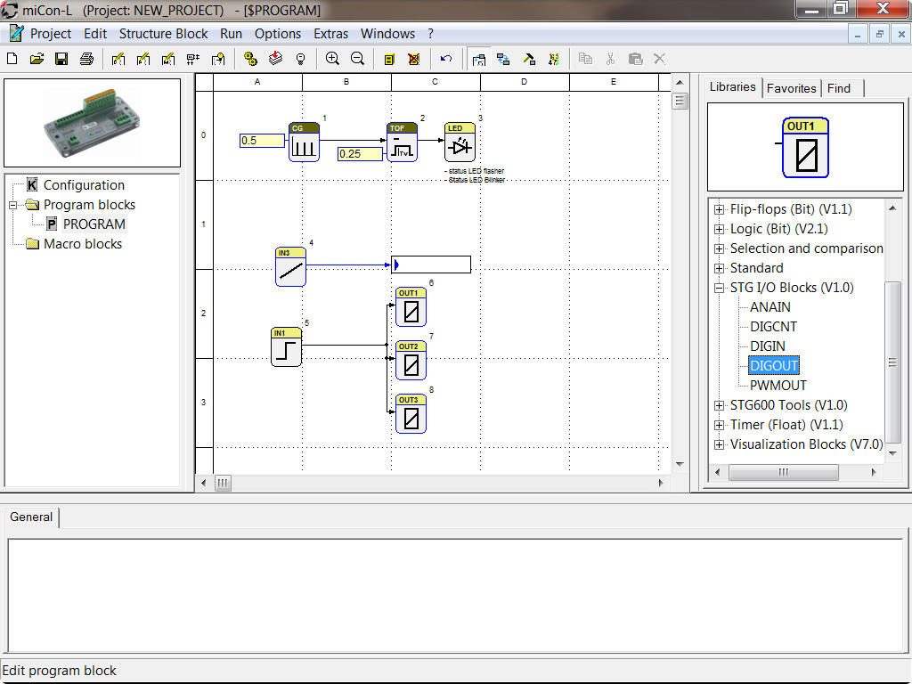
Programming the potentiometer: use function block “ANAIN” for an analog input
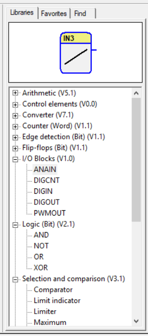
Drag the function block from the window above the library tree into the worksheet using drag-and-drop
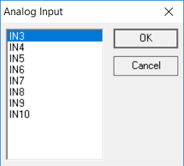
Choose IN3, as the potentiometer is plugged into input IN3 on the STG-600
Drag the numeric display into the worksheet
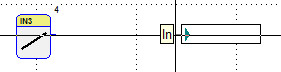
The connection between input and output will be generated by left-click on the output of the analog input, then click again on the input of the numeric display.
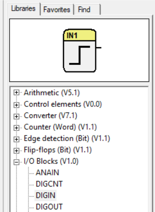
Programming the LEDs: insert the function block “DIGIN” for a digital input into the worksheet using drag-and-drop
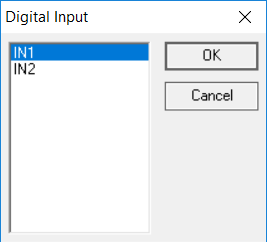
Choose IN1, as the switch is inserted in IN1 on the STG-600
Insert three digital outputs (“DIGOUT”) for the three LEDs (green LED on OUT1, yellow LED on OUT2 and red LED on OUT3) and connect them.
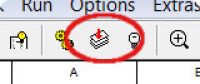
Download the program files on the STG-600
In online mode, you can see the blinking status LED, and when pressing the switch, the function blocks are flashing green. When twisting the potentiometer, you will see the resistance values in the numeric display.
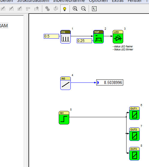
When pressing the switch, three LEDs will light up.